A lot of you may have seen this project on the 12/19/2018 edition of Hamnation in Randy, K7AGE’s projects segment.

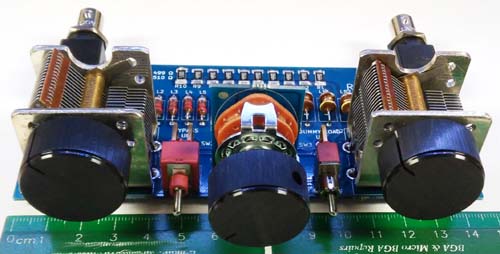
With the resurgence of interest in kit radios and QRP I was wanting to design a versatile tuner to pair with my uBITX and other radios I’m working on that was relatively compact and could be built into a case along with the radio. If you are interested in purchasing in board, kit or assembled form they will be ready around the first of January 2019 and available from our store here
My usual design philosophy is to minimize as much hand wiring as possible, particularly to controls and connections. I prefer being able to mount as many controls and connectors as possible directly to the PCB.
I looked at the low cost China designs and immediately disliked them due to the polyvaricon caps and hand-wound, tapped powder metal core design soldered to the back of a rotary switch. It rubbed my sense of repeatability, reliability, ease of assembly and general aesthetics the wrong way. I searched around and located some 380pF single gang air variable capacitors on Amazon that could be board mounted directly.
The next issue was finding a rotary switch with 9-12 poles that I could PCB mount and use to switch in a number of fixed inductors so the inductances would be repeatable. The switch requires an intermediate board in order to get it at right angles to the PCB like the air variables. The switch is also probably the limiting factor on the throughput power of the tuner. It is nominally rated for 1A so that would limit you to around 50W of RF.
Next was looking at any additional and useful bells and whistles that could be added without dramatically blowing up the size or cost. I decided the ability to bypass the tuner would be good as well as building in a low power dummy load. The toggle switch to the left of the inductor switch is to bypass the tuner when in the up position. The switch to the right switches in the 50 Ohm internal load.
After several days of simulations and calculations I came up with an optimized set of inductor values that were common values, in stock and had self resonances well above the frequency range they would be used at. In fact if you look closely at the board the first inductor has been replaced by a jumper wire because the stray inductance of the traces on the board were almost exactly the value of the lowest inductance. I couldn’t get it to tune well on 10m & 6m until I removed it and replaced it with the wire.
My choice of either BNC or SMA connectors may be controversial but there are simply no inexpensive right angle PCB mount SO-239 connectors that I could find. The mated length of PL-259/SO-239 is also very long and the BNC and SMA mated lengths are shorter and can be accommodated internal to a box or enclosure easier.
The resulting design is a bit larger than I would like, but the width is dominated by the rotary switch, toggle switches and air variables. It comes in at 5.8″ wide by about 2.5″ deep. Mounting holes are included so it can be solidly mounted. I could probably shave off a half inch in depth and about an inch in width if I drop the load, bypass switch and load switch. If there is some interest in creating a smaller one without those features let me know and I might work one up for my next board order.
I have modified the latest version 1.1 too eliminate surface mount components. The surface mount load resistors have been replaced with a single TO-220 packaged 50 Ohm 30W resistor with a heat sink. The new revision is still in testing and should be available in January 2019. I will be offering it as a bare board, kit or assembled. I’m working on finalizing the product on my ecommerce site here.
Features include:
- Compact size – 145mm x 65mm (PCB) with corner mounting holes
- BNC, SMA or direct wired input/outputs
- Tuner bypass switch
- Switch selected Internal 50 Ohm 30W load
- Pi Network tuner configuration for wide range tuning into loads less than or greater than 50 Ohms
- 12 position inductor switch with all inductors capable of 2.5A RMS RF
- 2 380pF Air variable capacitors with 500V max voltage rating
- Can be purchased as a bare board, kit or assembled.
- Note: Knobs not included
This design is released under the CERN OSH License Ver 1.2 and all of the documentation, bill of materials and board layout in KiCad will be posted to my github sites at github/celeritous or github/k5abl
